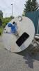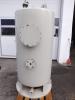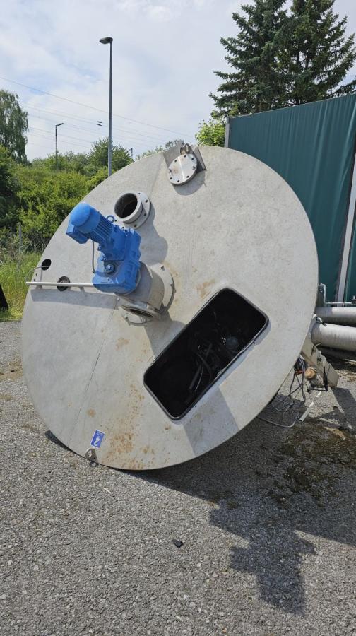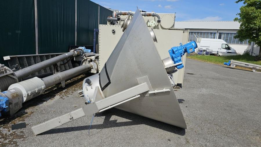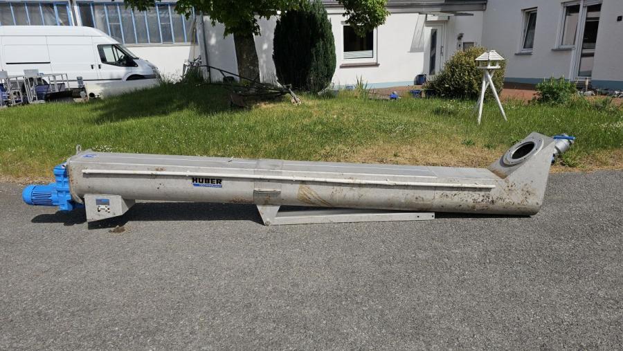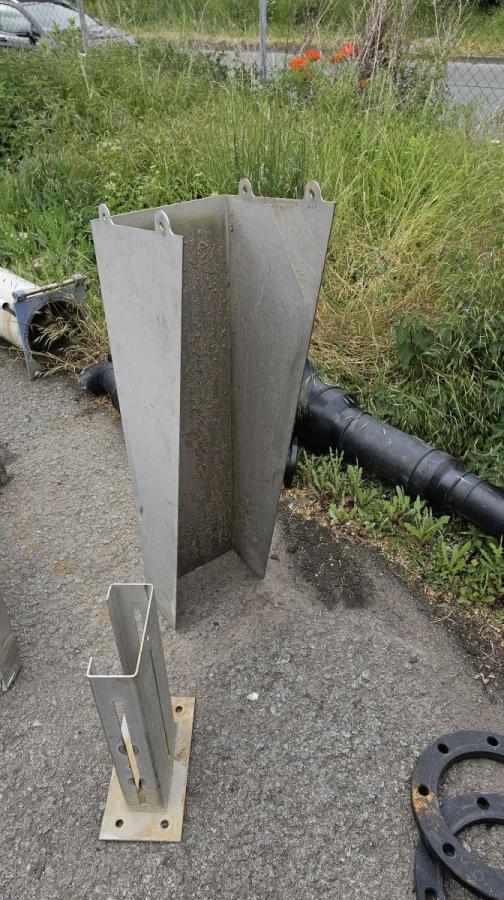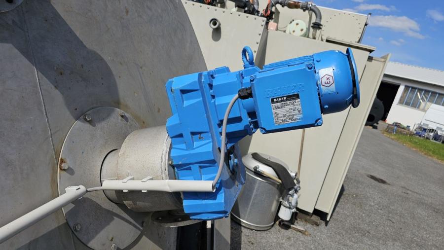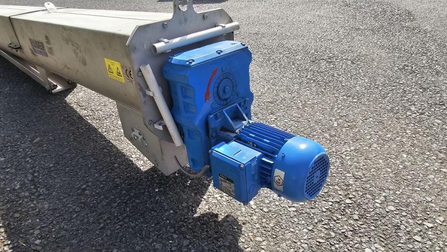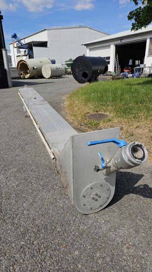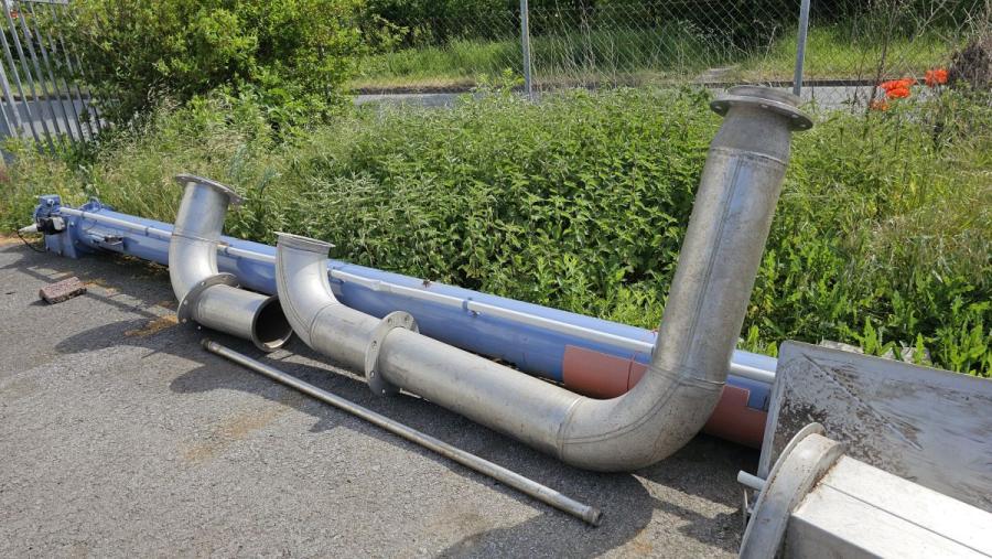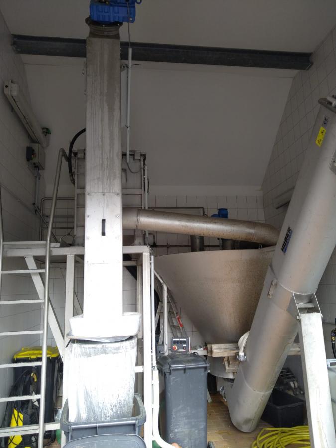
used COANDA sand washer / sand classifier / sand washer classifier
details to article: 30391
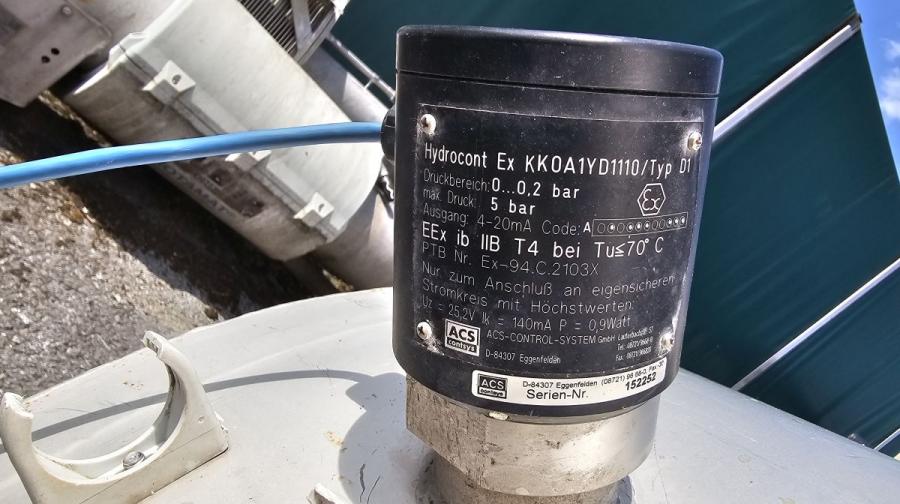
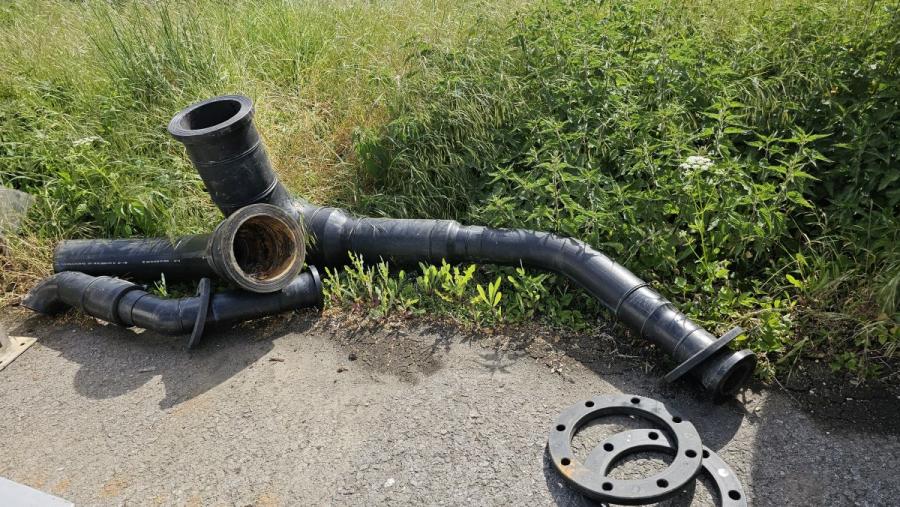
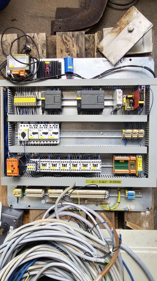
description: System for grit dewatering and separation The system was operated together with a Huber wastewater screening plant (see article number 30389). The corresponding pipework and a control panel with PLC control for this are available (see the last 4 pictures).
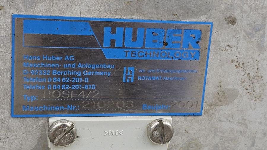
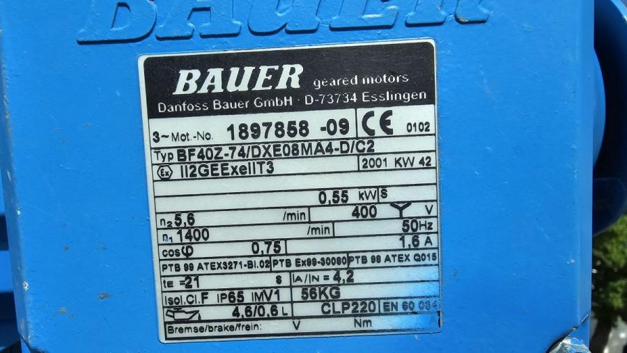
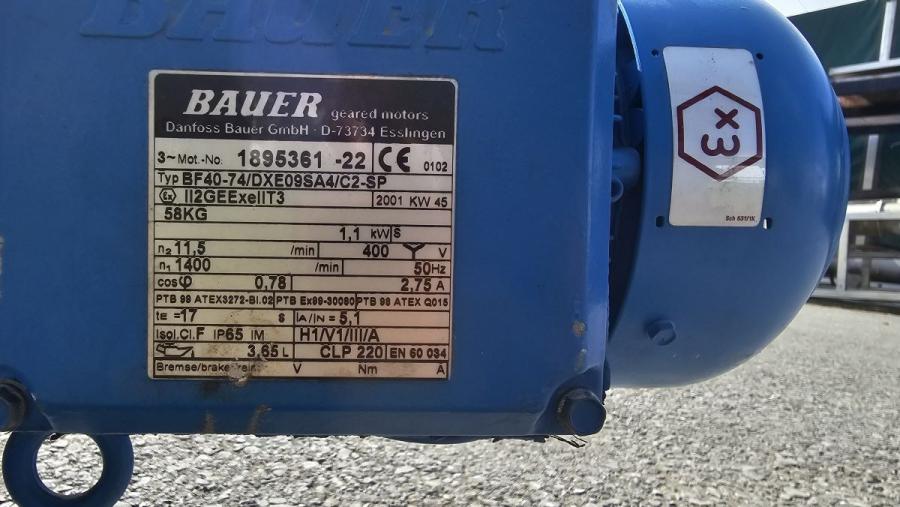
| Producer: | Huber |
| Typ: | ROSF4/2 |
| Year of manufacture: | 2001 |
| Pieces: | 1 |
| Condition: | gebraucht / used / second hand |
Alle Angaben, Bilder, Hinweise und Empfehlungen erfolgen nach bestem Wissen, je- doch ohne Gewähr. Änderungen der technischen Angaben bleiben vorbehalten.
informations about: separators The term separator in oilfield terminology designates a pressure vessel used for separating well fluids produced from oil and gas wells into gaseous and liquid components. A separator for petroleum production is a large vessel designed to separate production fluids into their constituent components of oil, gas and water. A separating vessel may be referred to in the following ways: Oil and gas separator, Separator, Stage separator, Trap, Knockout vessel (Knockout drum, knockout trap, water knockout, or liquid knockout), Flash chamber (flash vessel or flash trap), Expansion separator or expansion vessel, Scrubber (gas scrubber), Filter (gas filter). These separating vessels are normally used on a producing lease or platform near the wellhead, manifold, or tank battery to separate fluids produced from oil and gas wells into oil and gas or liquid and gas. An oil and gas separator generally includes the following essential components and features: 1. A vessel that includes (a) primary separation device and/or section, (b) secondary gravity settling (separating) section, (c) mist extractor to remove small liquid particles from the gas, (d) gas outlet, (e) liquid settling (separating) section to remove gas or vapor from oil (on a three-phase unit, this section also separates water from oil), (f) oil outlet, and (g) water outlet (three-phase unit). 2. Adequate volumetric liquid capacity to handle liquid surges (slugs) from the wells and/or flowlines. 3. Adequate vessel diameter and height or length to allow most of the liquid to separate from the gas so that the mist extractor will not be flooded. 4. A means of controlling an oil level in the separator, which usually includes a liquid-level controller and a diaphragm motor valve on the gas outlet. 5. A backpressure valve on the gas outlet to maintain a steady pressure in the vessel. 6. Pressure relief devices. Separators work on the principle that the three components have different densities, which allows them to stratify when moving slowly with gas on top, water on the bottom and oil in the middle. Any solids such as sand will also settle in the bottom of the separator. The functions of oil and gas separators can be divided into the primary and secondary functions which will be discussed later on. Separation of oil from gas may begin as the fluid flows through the producing formation into the well bore and may progressively increase through the tubing, flow lines, and surface handling equipment. Under certain conditions, the fluid may be completely separated into liquid and gas before it reaches the oil and gas separator. In such cases, the separator vessel affords only an enlargement to permit gas to ascend to one outlet and liquid to descend to another. From Wikipedia, the free encyclopedia | ||||||||||||||||||||||||||||||||||||||||||||||
| email: mail@tipp-international.de | ||||||||||||||||||||||||||||||||||||||||||||||
| Internet: www.tipp-international.de | ||||||||||||||||||||||||||||||||||||||||||||||